BlinkThorLabs
Holding the RRC Lite Controller: A Hands-On Teardown
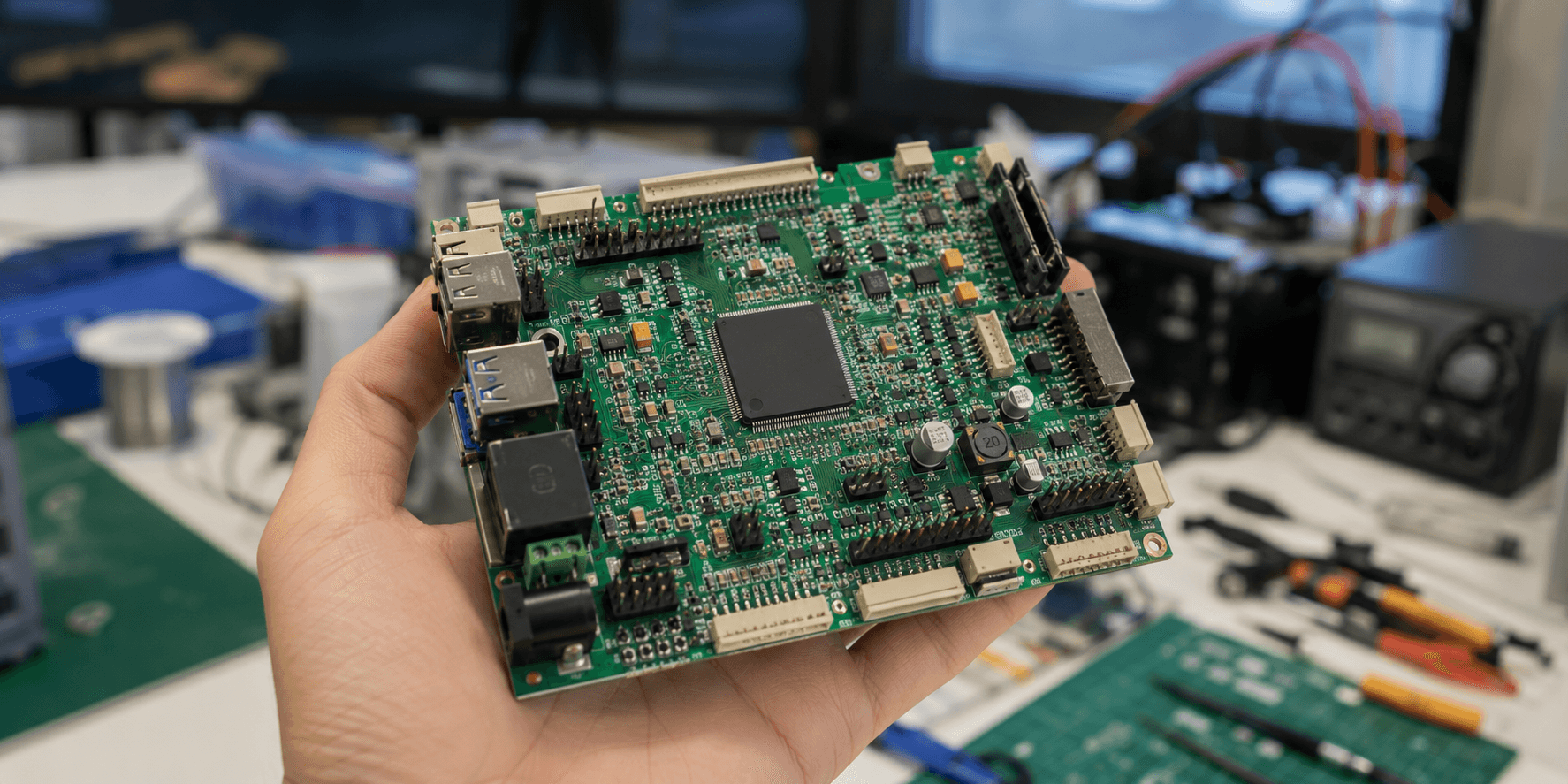
Not a datasheet. Just me, the board, and every little cluster of components I almost overlooked the first time.
The first thing that actually surprised me about the RRC Lite controller, before I'd even looked closely at a single component, was how light it felt in my hand — I'd built up a mental picture of something a bit heavier, given how much it's asked to coordinate on this robot, and instead it's this thin, unassuming green rectangle that barely registers as a weight at all. The second thing, immediately after, was the sheer density packed around that square chip sitting almost dead center — rows of tiny passive components crowded in close, like the board's real estate around that one chip is the most contested property on the whole thing. Let's walk around it properly, the way I did the first time I actually turned it over in my hands.
The Chip in the Middle: STM32F407VET6
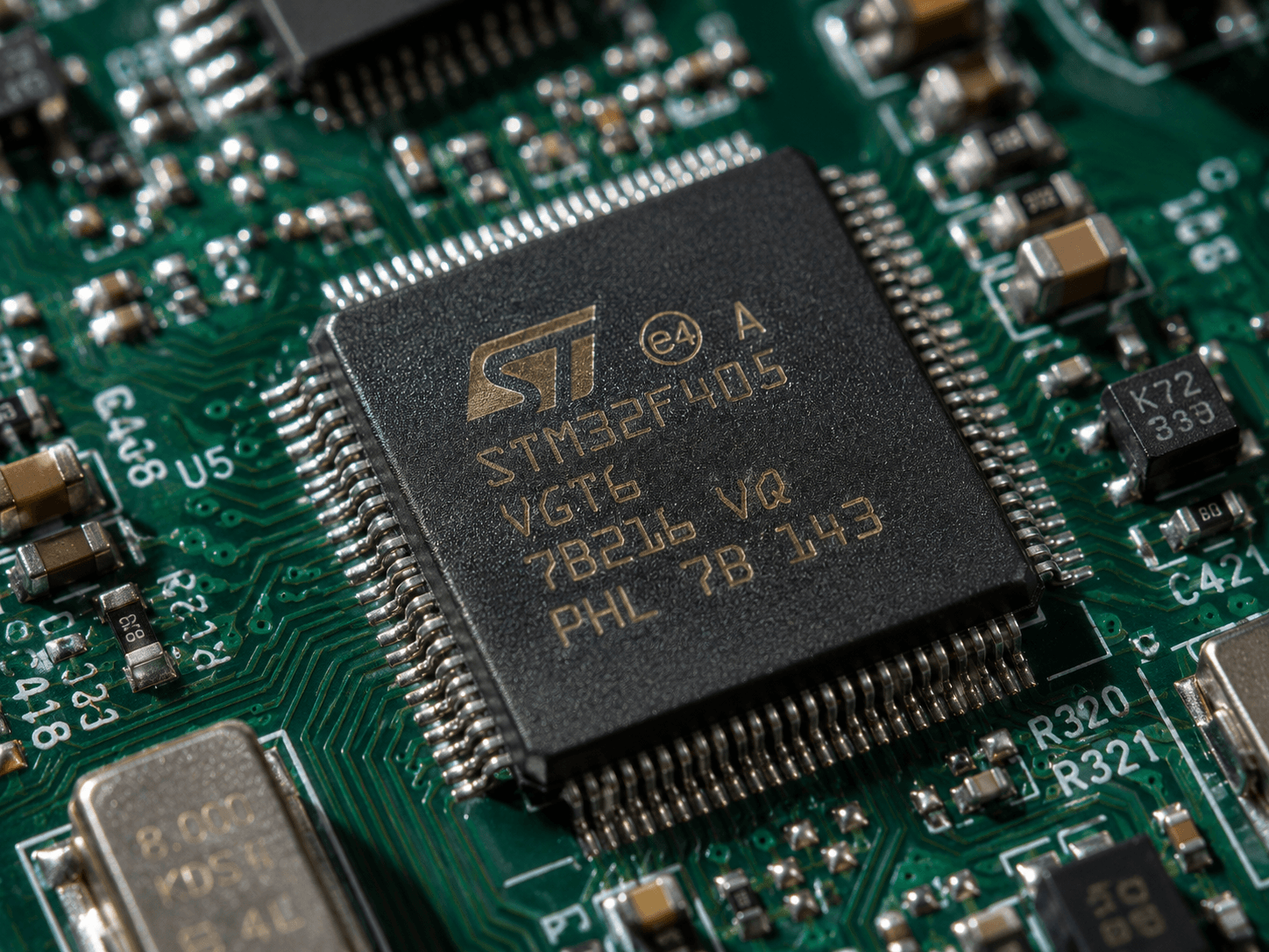
Everything on this board radiates outward from this one square chip — an STM32F407VET6, an ARM Cortex-M4 core clocked at 168MHz, with 512KB of flash and 192KB of RAM. Numbers on a spec sheet don't mean much until you actually count what's attached to this chip: 82 IO pins, which sounds like an almost absurd number for something driving what is, ultimately, a small wheeled robot.
Except once you actually trace where those pins go, it stops feeling excessive and starts feeling necessary. This isn't a chip driving one motor and reading one sensor. It's the single point of coordination for every servo, every wheel motor with its own encoder feedback, every status LED, every button, every IMU reading — all of it converging on this one chip's pin count before any of it gets summarized and handed up to the Raspberry Pi. 82 pins is what it actually costs, in hardware terms, to be the thing standing in the middle of all of that.
Servo Ports and the Servo Bus, Side by Side
Moving outward from the chip, the first connector cluster I actually recognized on sight was a small group of PWM servo headers, sitting near a separate servo bus port — these are for exactly what you'd guess, arm and pan-tilt mechanisms, but the fact that there are two distinct kinds of servo connection here, rather than one generic header repeated, is worth pausing on. The PWM ports are simple, direct pulse-width control — send a signal, servo moves to a position, no feedback path. The servo bus port is a different animal entirely, supporting addressable, chainable smart servos that can report their own position and status back to the controller rather than just blindly receiving a command. Two different servo philosophies, sitting a few centimeters apart on the same board, depending on which kind of arm or gimbal hardware you actually plug in.
Four Motor Ports, Four Wheels, One Chip Watching All of Them
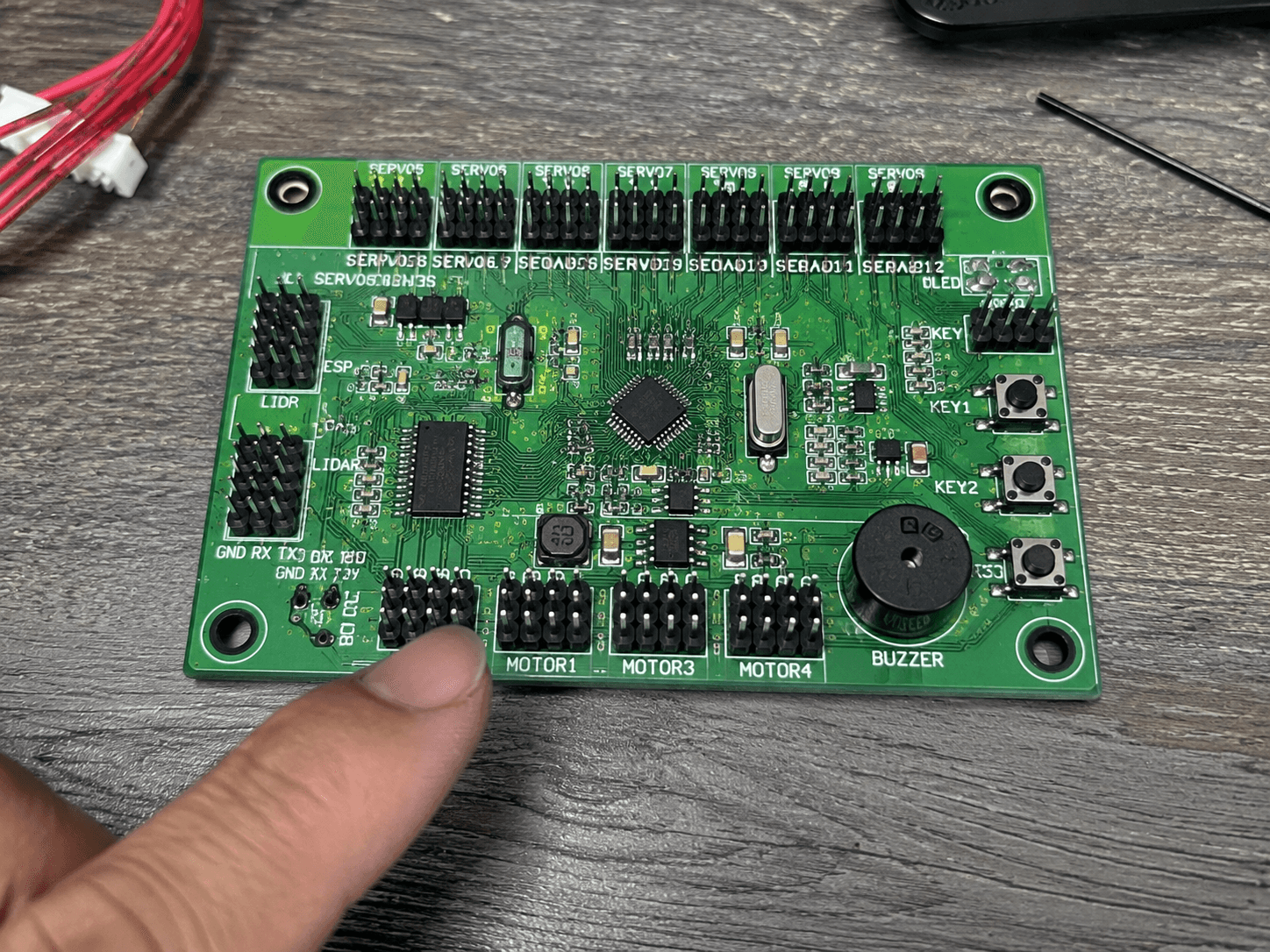
Next cluster: four dedicated motor-with-encoder ports, wired for simultaneous control of up to four independently driven wheels. This is where the chip's pin budget really starts making sense — each of these four ports isn't just a motor drive line, it's a motor drive line plus a paired encoder feedback line, meaning the chip isn't just telling four motors what to do, it's simultaneously listening to four separate streams of "here's what you actually did" coming back in real time. On an Ackermann chassis like the one I've been running, not all four ports necessarily drive independently-steerable wheels the way a genuine four-wheel-independent-drive platform would use them — but the header count is clearly built to serve whichever drivetrain configuration gets bolted onto this same base controller, Ackermann or otherwise.
The Small Cluster I Almost Skipped Past
Tucked into a corner, easy to walk past if you're focused on the bigger, more obviously important connectors: two programmable RGB LEDs, one small user LED, two general-purpose tactile buttons, and — separate from all of that — a dedicated reset button wired specifically to the STM32 chip itself, distinct from anything that resets the Raspberry Pi. That last detail matters more than it looks like it should: it means you can reset just the low-level motor/servo controller without taking down the Pi's entire ROS2 stack alongside it, which is exactly the kind of small hardware decision that saves you a genuinely annoying amount of reboot time the first time you actually need it mid-debug session.
The Detail That Actually Made Me Stop and Look Twice
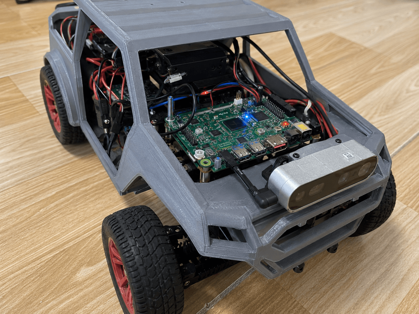
Here's the one that genuinely surprised me: this board has two USB ports, and they are not doing the same job at all. The first is exactly what you'd expect — a straightforward USB connection for flashing firmware onto the STM32 and serial communication with it during development. The second port, sitting right next to it, is something I didn't expect on a "controller board" at all: a dedicated 5V/5A power output, specifically there to feed power back to the Raspberry Pi, rather than the more intuitive assumption that power flows from the Pi down to peripherals. The RRC Lite isn't just a peripheral the Pi commands — it's also, quietly, part of the power delivery chain keeping the Pi itself running.
Right beside the main chip, easy to miss if you're not specifically looking for it, sits a small IMU — a QMI8658 — mounted directly on this board rather than somewhere else on the chassis. The controller isn't just relaying motor and servo commands outward; it's independently sensing its own orientation and motion, right at the source, before that data ever needs to travel anywhere else on the robot.
What This Board Actually Is
Coming away from actually handling this thing rather than just reading its spec sheet, the label that fits isn't "a bigger Arduino." An Arduino is a general-purpose microcontroller board waiting for you to decide what it's for. This is something much more specific and, honestly, more interesting: a dedicated hardware coordinator sitting directly between the Raspberry Pi's high-level ROS2 decision-making and every single physical actuator and sensor the robot actually has — servos, wheel motors with encoder feedback, its own onboard IMU, its own status indicators, and even a slice of the Pi's own power supply. The Pi thinks about where the robot should go. This board is the thing that actually makes sure it happens, watches it happen, and — with that second USB port — helps keep the thing doing the thinking powered on in the first place.