BlinkThorLabs
An Apology to the Small Components on the RRC Lite Board
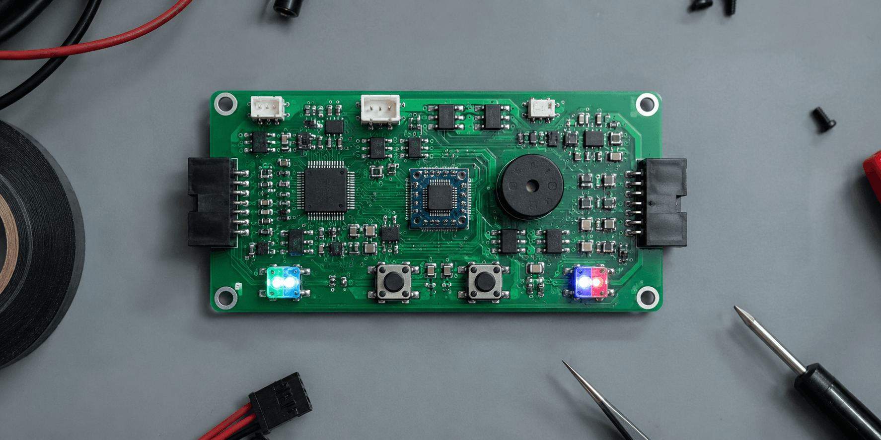
Five parts I walked right past on my way to the big square chip in the middle. They deserved better.
The first time I looked at this board, my eyes went straight to the STM32 chip in the center and mostly stayed there — it's the biggest thing on the board, it's obviously the "important" part, and everything smaller around it registered as background detail. I was wrong about most of it, and this is my belated, slightly overdue apology to five small components I should have paid attention to much sooner.
1. The Two RGB LEDs
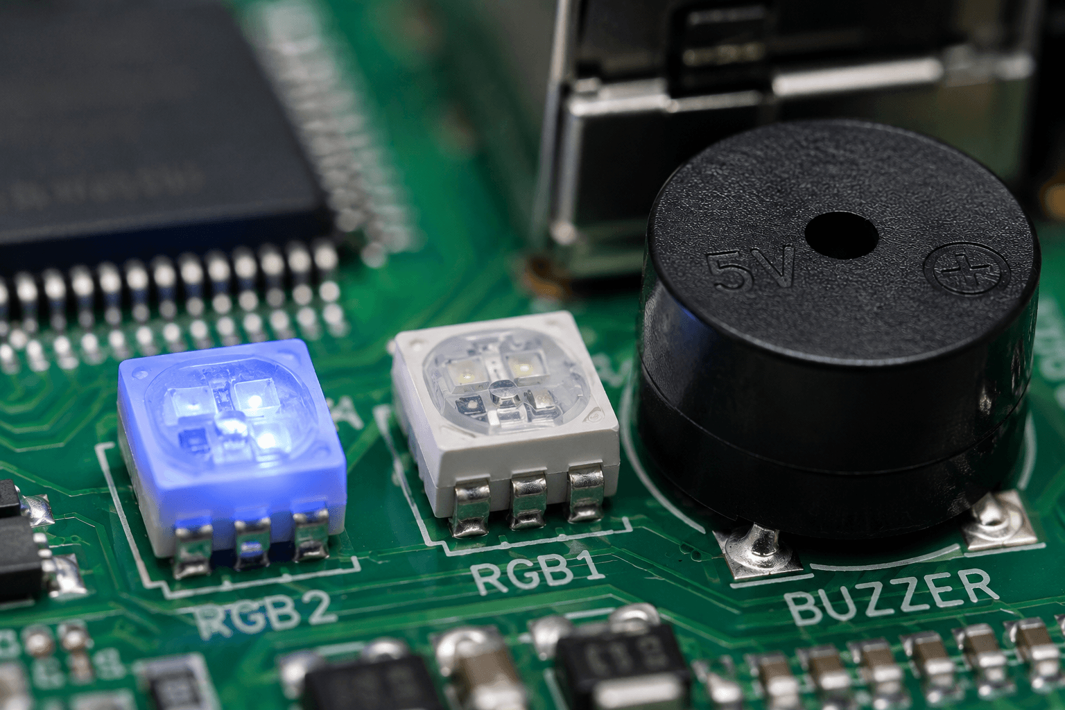
Thought they were just there to blink prettily. Small, colorful, the kind of thing that reads as "nice touch" rather than "load-bearing feature" on first glance.
What they're actually doing: these are the board's only visual status channel when there's no screen attached, and they're driven through the exact same structured command system as everything else — PACKET_FUNC_LED, with explicit on-time and off-time parameters specified in milliseconds. That's not a decorative blink pattern. That's a genuinely programmable signaling system, capable of encoding distinct states (steady, slow pulse, fast pulse, specific color combinations) as real diagnostic information, in exactly the situation where you most need it — when the board is running headless and a color and blink pattern might be the only thing telling you whether it's booted cleanly, waiting on something, or stuck.
2. The Tiny Buzzer
Thought it was there to make a cute confirmation "beep." Genuinely the component I paid the least attention to for the longest time — small, round, easy to mentally file under "the thing that goes beep."
What it's actually doing: PACKET_FUNC_BUZZER takes a custom frequency parameter in Hz, which means this isn't a fixed single-tone beeper — it's a component capable of encoding meaningfully different alert signatures purely through frequency and duration choices. A short high-pitched tone can mean something entirely different from a longer low-pitched one, all from the same tiny component, with no additional hardware required. I'd been treating it as a single-purpose novelty when it's actually a flexible, if modest, audio signaling system.
3. The Two User Buttons and the Separate Reset Button
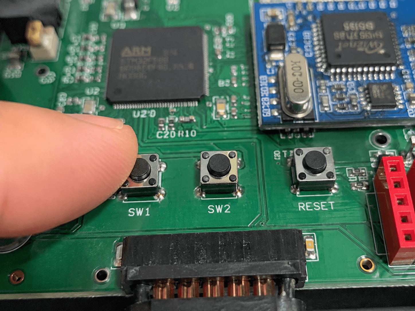
Thought they were simple on/off switches. Buttons are buttons — press it, something happens, that's the whole story, or so I assumed.
What they're actually doing: each user button can distinguish between four separate interaction types — press, hold, click, and double-click — all reported back to the host individually through PACKET_FUNC_KEY. That's not a switch. That's a small gesture-recognition input device disguised as a switch, capable of triggering four genuinely different behaviors from the exact same physical button depending purely on how you interact with it. And the separate reset button, wired specifically to the STM32 rather than the whole system, quietly solves a problem I didn't appreciate until I actually needed it — resetting just the low-level controller without taking down the Raspberry Pi's entire ROS2 stack along with it.
4. The QMI8658 IMU Sitting Quietly Next to the Main Chip
Thought it was some kind of auxiliary support component, the way a small unlabeled chip near a "real" chip often gets mentally filed as supporting cast rather than a lead role.
What it's actually doing: this small sensor is continuously streaming full 6-axis accelerometer and gyroscope data back to the host via PACKET_FUNC_IMU, and it is, quietly, the foundation underneath every piece of the robot's orientation and motion estimation. Nothing about pose, tilt, or motion sensing happens without this specific small component doing its job correctly and continuously. I owe this one a genuine apology — it's not supporting cast at all. It's one of the board's most structurally important components, just packaged in a footprint too small to look the part.
5. The 5V/5A Power Port Next to the Serial Port
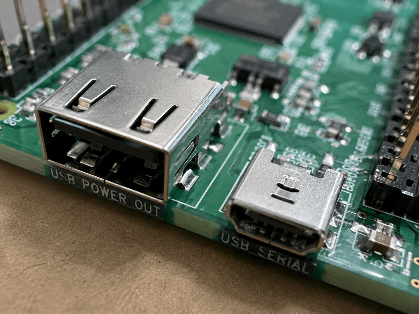
Thought it was just another serial/data connector, easy to mentally lump in with its neighbor since they sit right next to each other and look, at a glance, like variations on the same kind of port.
What it's actually doing: the documentation is specific and unambiguous about this one — this port exists purely to deliver 5V/5A power back to the Raspberry Pi, and it is explicitly not meant for data communication of any kind. This is the one on this list I'm most glad I caught before making an actual mistake with it, rather than after — mixing up a dedicated power-delivery port with a data port is exactly the kind of assumption that goes fine until, one day, it very much doesn't.
The Actual Lesson Here
None of these five components are hard to understand once you actually read the documentation and trace what packet type each one uses — the STM32 in the center just has enough visual gravity to make everything smaller around it look like an afterthought, when in practice almost none of it actually is. This board doesn't really have decorative parts. It has parts I hadn't bothered reading about yet. There's a difference, and it took genuinely picking up the datasheet and the packet reference, rather than just the chip in the middle, to actually see it.