BlinkThorLabs
Building MentorPi-A1: From a Box of 3D-Printed Parts to a Robot That Drives Itself
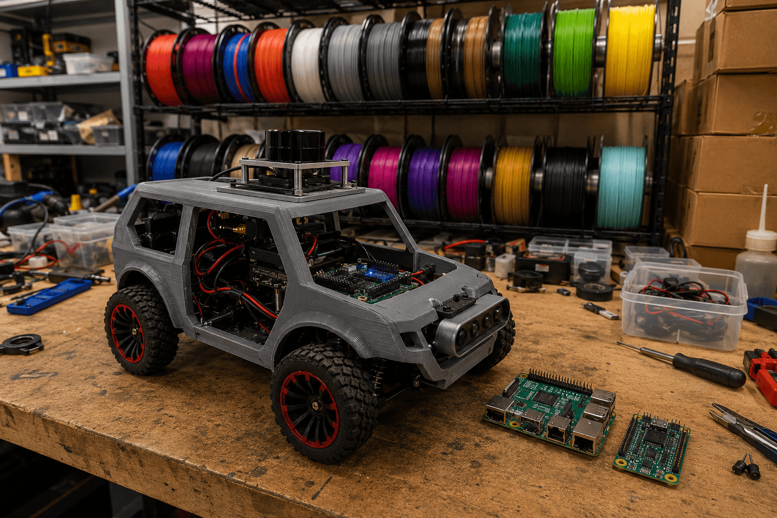
Ackermann chassis, ROS2 on a Raspberry Pi 5, and the specific joy of hearing a buzzer confirm your first boot actually worked.
I've built enough robotics kits at this point to know the honest truth about them: the marketing photo always shows the finished robot looking clean and inevitable, and the actual build always involves at least one moment of quietly hunting through a pile of packing foam for a screw that rolled somewhere it had no business rolling. This is the real build log for MentorPi-A1 — Ackermann steering chassis, ROS2 running on a Raspberry Pi 5 — warts, missing-screw moment, and all.
Stage 1: Unboxing, and Actually Checking the Packing List for Once
I have a bad habit of unboxing a kit, getting excited, and starting to assemble before actually confirming everything's in the box — a habit that has cost me real time on past projects when a missing part turns up halfway through assembly. Not this time. Packing list, laid out piece by piece on the workbench, checked off one at a time:
- RRC Lite controller board — present, still in its anti-static bag
- Raspberry Pi 5 — present, and noticeably warmer-feeling in hand than I expected for something not yet powered, purely psychological I'm sure
- 64GB microSD card, pre-loaded — present, taped to a small card inside the box that I almost threw away with the packing paper before noticing text on it
- Cooling fan — present, tiny, the kind of component that's very easy to lose in packing foam if you're not paying attention
- TOF LiDAR unit — present, well-padded in its own foam cutout
- 3D depth camera — present
- Wireless handheld controller, two AA batteries included — present
- A small EVA foam ball, presumably for color-tracking test scenarios later — present, and genuinely the item I was least expecting to find in this box
Everything accounted for. Small, satisfying win before a single screw gets turned.
Stage 2: Getting Acquainted With the 3D-Printed Shell, One Panel at a Time
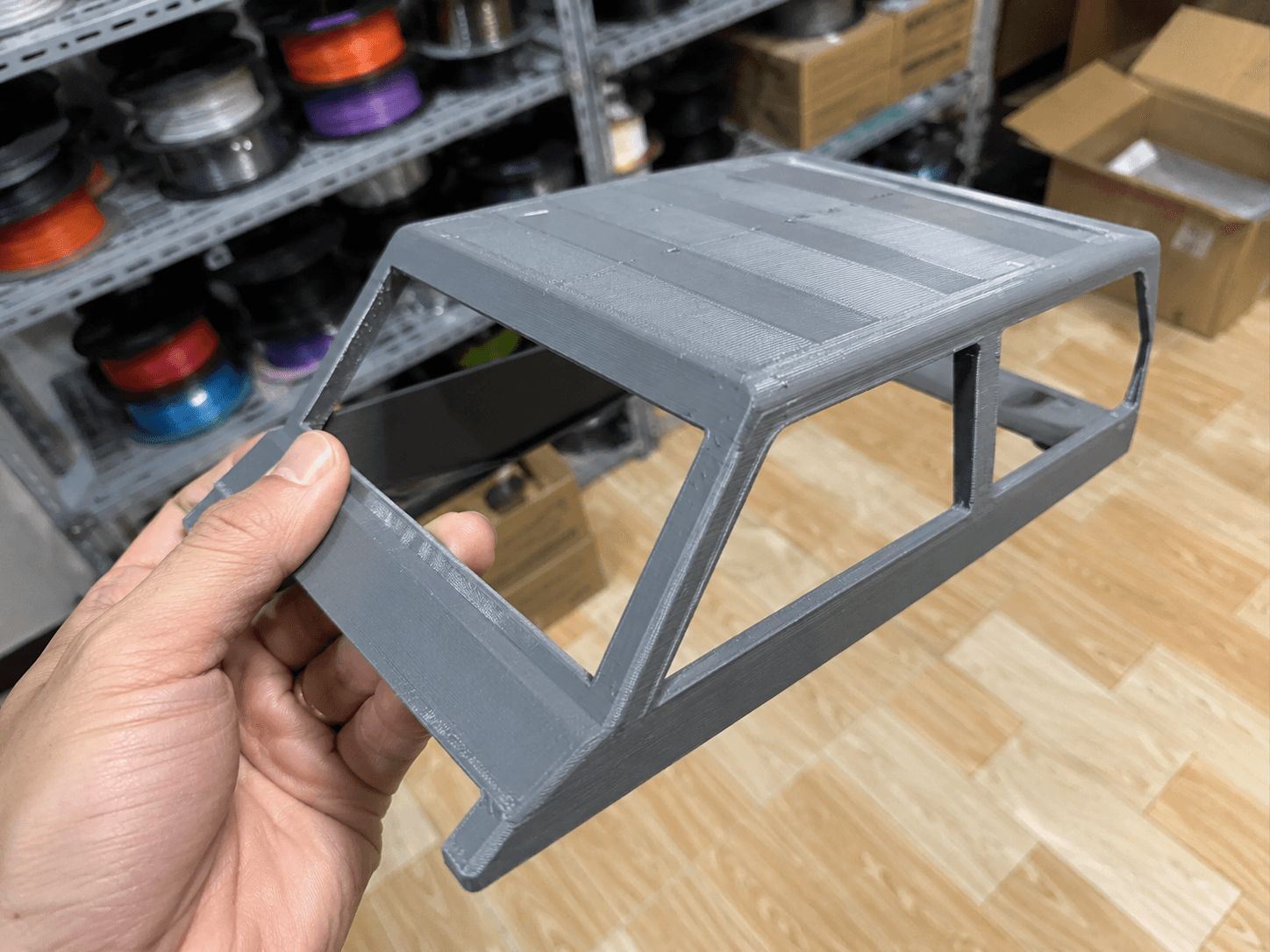
This is the part of any 3D-printed kit build that rewards patience over enthusiasm. I picked up each shell piece — roof panel, front bumper, rear bumper — one at a time, held it under the workbench lamp, and actually looked at the layer lines before doing anything else. You can tell a lot about how a panel is going to behave during assembly just from how consistent those layer lines are across a surface; a panel with visibly uneven layer spacing in one corner is telling you, in advance, exactly where it's most likely to need a little persuasion to seat correctly.
Cross-referencing each piece against the assembly diagram, most of it matched up cleanly. Two edges — one on the front bumper, one where the roof panel meets the main chassis rail — needed a light pass with a small file, just enough to true up what was clearly a slightly-tight print tolerance rather than a genuine part defect. Nothing dramatic, the kind of five-minutes-per-edge correction that's completely normal for a 3D-printed kit and not worth worrying about, but worth doing carefully rather than forcing a tight-fitting panel and risking a hairline crack in the plastic.
Stage 3: Wiring the Open Cockpit, and the Screw That Went Missing
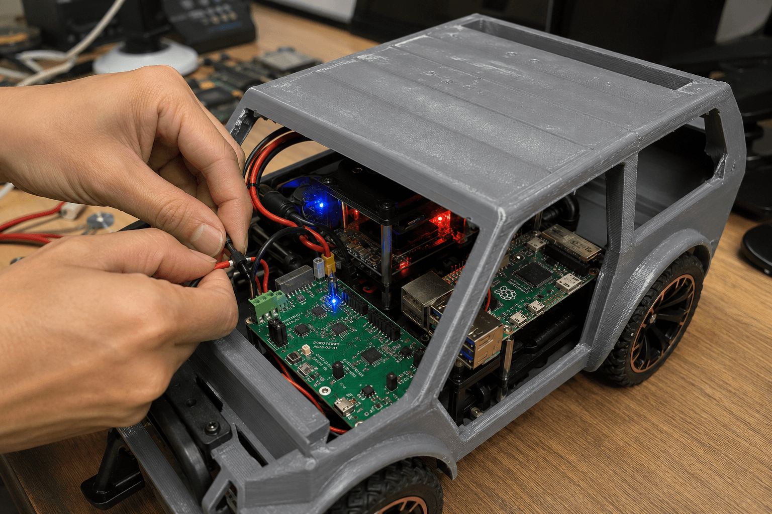
With the shell test-fitted and set aside, the actual electronics went in with the chassis still open — deliberately leaving the "cockpit" accessible rather than closing up the shell first, since it's much easier to seat a controller board and route wiring cleanly before everything's boxed in.
The RRC Lite controller mounted onto its standoff points without drama. Connecting the red and black power leads was the moment I was most careful about, for the obvious reason — reversed polarity on a first power-up is exactly the kind of mistake that turns an exciting build session into a very different kind of evening. Leads connected, checked twice against the wiring diagram, checked a third time mostly for my own peace of mind.
This is also, predictably, when a screw went missing. A small mounting screw for the Raspberry Pi 5's standoff bracket — I set it down for approximately four seconds to reposition the board, and it was gone, presumably nestled somewhere in the coil of leftover 3D-printing support material sitting on the corner of the bench, which I'd been slowly accumulating without thinking of it as "a place small metal objects go to hide" until exactly this moment. Found it about six minutes later, genuinely by accident, while moving that same coil of material out of the way to get better light on the chassis. Every build has one of these moments. This was this build's.
Raspberry Pi 5 finally bolted down cleanly, cabling routed to keep the fan's airflow path clear, RRC Lite's status LED visible: a small red glow, waiting for full power-up, next to an equally small green indicator that I correctly guessed meant "logic power good, main power not yet applied" before actually checking the documentation to confirm I'd guessed right.
Stage 4: The First Power-On, and the Buzzer That Made It Real
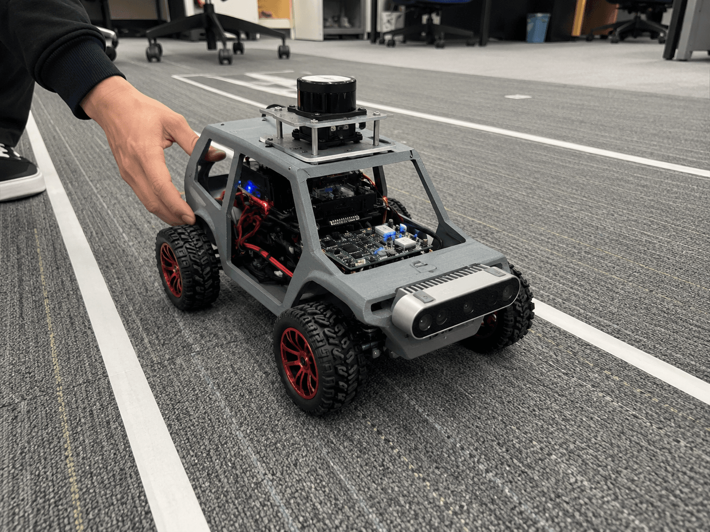
Everything closed up, shell panels seated (filed edges fitting noticeably better this time), and the actual first power-on moment arrived with the specific, slightly irrational nervousness that comes right before flipping the switch on something you spent an entire evening assembling by hand.
Power on. Red LED steady, then the green LED joining it a moment later — main power confirmed. And then, a few seconds after that, a single clean buzzer tone — the start_node.service completing its boot sequence, ROS2 nodes coming up cleanly on the Raspberry Pi 5, confirmed audibly before I'd even had a chance to pull up a terminal to check logs myself. There's something genuinely satisfying about a build giving you an audible "I'm alive and everything came up correctly" signal rather than making you go hunting through a log file to confirm the same thing.
Set the robot down on a test mat with painted lane lines — nothing fancy, just enough to give the Ackermann steering geometry something to actually navigate around — grabbed the wireless controller, and ran it through basic manual driving: forward, reverse, a full turning radius test in both directions to confirm the Ackermann steering geometry was behaving the way the assembly diagram promised it would.
It drove. Not autonomously yet — that's a project for the coming weeks once I actually start working with the LiDAR and depth camera data properly — but the chassis moved cleanly, steering responded correctly to input, and after an evening of filed edges, a hunted-down screw, and one very carefully double-checked set of power leads, watching it complete a clean turning circle on its own wheels was exactly the payoff the whole build had been working toward.
What's Next
The EVA foam ball is clearly foreshadowing a color-tracking demo I haven't built yet, and the LiDAR and depth camera are currently doing nothing but sitting there mounted and ready, waiting for actual perception code. That's the next build log. Tonight was just about proving the chassis, the wiring, and the boot sequence were solid enough to build the interesting part on top of — and after one missing screw and two filed edges, they are.