BlinkThorLabs
CAN-FD Bit Timing: The Math Nobody Explains Properly
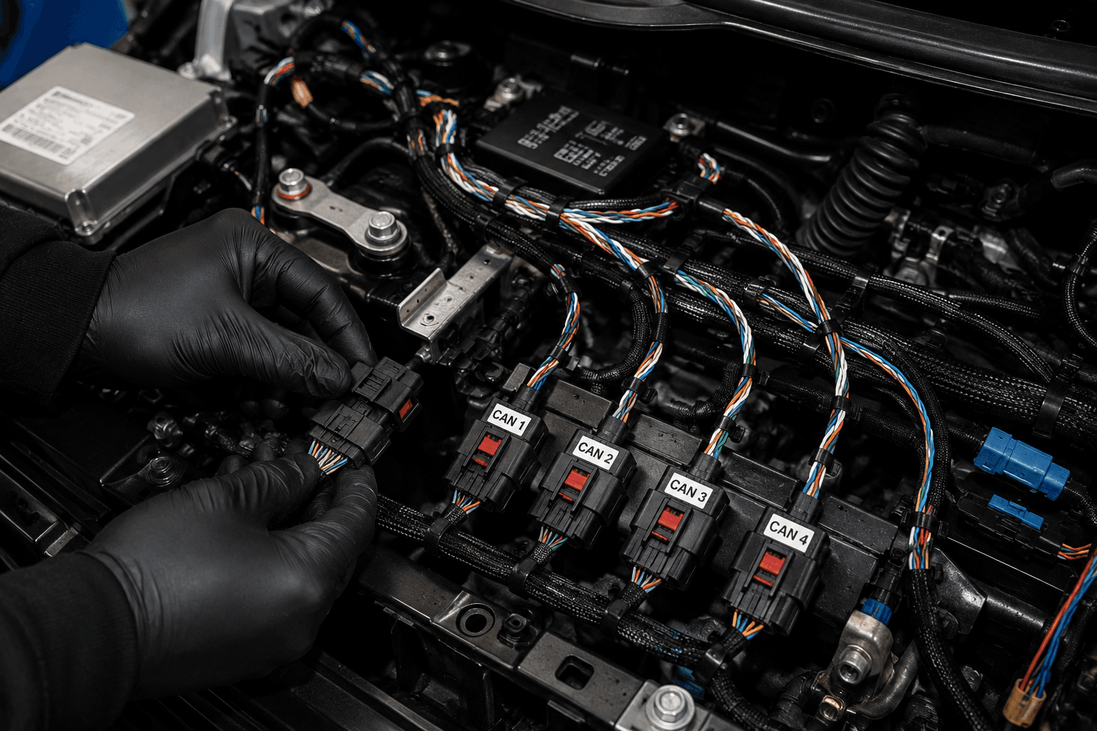
Sample points, propagation delay, and how one oscillator tolerance broke a whole harness.
Most CAN-FD documentation explains bit timing the same way: define the segments, show the formula, move on. Then you go build a real harness, three ECUs go bus-off intermittently under vibration and temperature cycling, and none of the reference material tells you why. This is the explanation we wish we'd had before that happened to us — the concepts, the actual math, and a real case where a 0.1% clock tolerance took down an entire network.
What Actually Went Wrong
A four-node CAN-FD network — gateway, two sensor ECUs, one actuator ECU — passed every bench test at room temperature. In the vehicle, after a few hours of driving, one of the sensor ECUs would intermittently go bus-off, recover, and repeat every 20-40 minutes. No single node was ever consistently the problem. Swapping harness sections didn't fix it. Swapping the "bad" ECU for a spare didn't fix it either.
The eventual finding: bit timing had been configured using the arbitration-phase defaults from a reference design, without re-verification for this network's actual cable length and node count. Under thermal drift, the accumulated timing margin — already thin — occasionally went negative on one node, causing a bit sampling error that CAN's error-detection correctly flagged as a form error, incrementing that node's error counter until it hit bus-off threshold. It wasn't a broken wire. It was arithmetic that had never been checked.
The Building Blocks
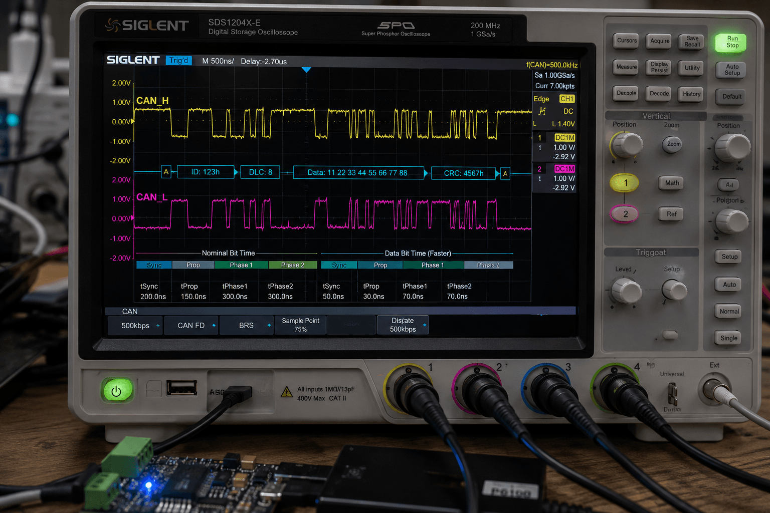
CAN bit timing divides each bit period into four segments, all specified in units of Time Quanta (TQ) — a fixed fraction of the bit time, derived from the CAN controller's oscillator:
Segment | Purpose |
|---|---|
SYNC_SEG | Always exactly 1 TQ. Nodes resynchronize their bit timing here on every recessive-to-dominant edge. |
PROP_SEG | Compensates for physical propagation delay — signal travel time down the bus, plus transceiver delays, in both directions. |
PHASE_SEG1 | Buffer before the sample point; can be extended during resynchronization if the edge arrives late. |
PHASE_SEG2 | Buffer after the sample point; can be shortened during resynchronization if the edge arrives early. |
The sample point is where the receiving node actually reads the bit value — positioned at the boundary between PHASE_SEG1 and PHASE_SEG2. For CAN-FD arbitration phase, sample points are typically placed around 75-80% into the bit time; for the faster data phase, often lower (60-70%) to leave more margin for the tighter timing.
The Synchronization Jump Width (SJW) caps how much PHASE_SEG1 or PHASE_SEG2 can be adjusted on any single resync event — it's the filter's speed limit, preventing one noisy edge from over-correcting the bit timing.
The Math
Propagation segment sizing has to cover the full round-trip delay budget:
t_PROP ≥ 2 × (t_bus_driver + t_bus_wire + t_bus_receiver)
For a wire, propagation delay is roughly 5 ns/meter. On a 10-meter run with transceiver delays of ~150 ns each way, that's:
t_PROP ≥ 2 × (150ns + 50ns + 150ns) = 700ns
At 500 kbit/s arbitration (2 µs bit time) with, say, a 20 MHz clock (50 ns per TQ), that 700 ns alone consumes 14 TQ — worth noting because on a longer or more complex harness, PROP_SEG can eat a surprisingly large share of the available quanta before you've allocated anything for phase buffering.
Oscillator tolerance is the other half of the budget, and it's the part most reference designs under-check. The maximum tolerable oscillator error, per node, so that resynchronization can still keep the network aligned, is bounded roughly by:
Δf_max ≤ min( SJW / (2 × bit_time_in_TQ) , PHASE_SEG_min / (2 × bit_time_in_TQ) )
The intuition: every bit, each node's local clock error accumulates a small phase drift relative to the transmitting node. SJW has to be large enough to correct that drift every bit, or error accumulates across the frame and phase eventually walks past the sample point.
The Case Study, With Numbers
Here's what tripped up our four-node network. Each node used an oscillator rated at ±0.1% tolerance — a spec sheet number that looks harmless. The network configuration had SJW set to 1 TQ, tuned tight to maximize sample point placement flexibility for signal integrity reasons.
With two nodes at opposite ends of that tolerance — one running +0.1% fast, one running -0.1% slow — the relative clock error between them was 0.2%, not 0.1%. Over a CAN-FD data-phase bit time built from, say, 10 TQ, that relative drift per bit was:
0.2% × 10 TQ = 0.02 TQ per bit
That doesn't sound alarming on its own — but frames aren't one bit long. A 64-byte CAN-FD payload frame, including header/CRC overhead, can run past 600 bits before the next hard resync opportunity (which only occurs on the next recessive-to-dominant edge, i.e., the next frame's SOF, not within a single frame beyond periodic resyncs from bit stuffing edges). Depending on stuff-bit frequency in the payload, the worst-case gap between resync opportunities could be several dozen bits — and at 0.02 TQ drift per bit, a 30-bit gap without a stuffing edge accumulates 0.6 TQ of unrecovered phase error, more than half of a 1 TQ PHASE_SEG2 buffer in a tight configuration.
Under stable room temperature, oscillator error was well under the ±0.1% worst-case spec, and the system had enough margin. Under the thermal cycling of a real vehicle, drift approached the spec's actual bound during specific temperature transients, and that's exactly when the intermittent bus-off appeared — a timing margin that was adequate in the lab and inadequate in the field, because the lab never exercised the oscillator across its full rated range.
The fix was not exotic: increase SJW from 1 TQ to 2 TQ (giving the resync mechanism twice the correction budget per event), and re-verify total oscillator tolerance budget using the actual worst-case combination of all four nodes' oscillator specs, not the nominal case. Bus-off events did not recur across 200+ hours of subsequent thermal-chamber and vehicle testing.
Tools for Getting This Right Before It Ships
You do not need to do this arithmetic by hand on a real project, but you do need to actually run the calculation rather than copying timing register values from a reference design that was tuned for a different harness topology.
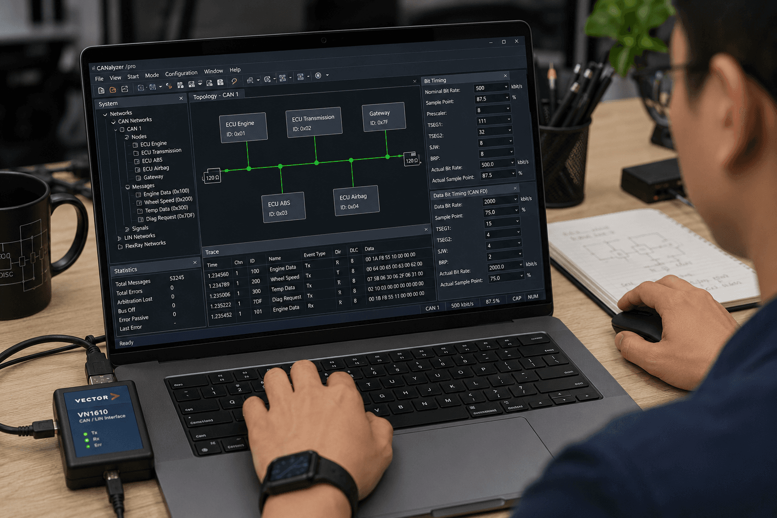
- Vector CANoe / CANalyzer bit timing calculators will compute achievable sample points and propagation margin directly from your target bit rate, oscillator frequency, and cable length inputs — use this before hardware exists, not after a bus-off shows up.
- Kvaser's bit timing calculator (free, web-based) is a fast way to sanity-check a specific configuration without a full toolchain, useful for a quick second opinion.
- Your MCU vendor's CAN-FD peripheral configuration tool (e.g., NXP S32 Design Studio, Infineon's timing calculator) will usually surface the exact TQ breakdown your silicon will actually use — worth cross-checking against the generic calculators above since specific controllers can have slightly different quantization behavior.
- For anything going into production, build a small spreadsheet that takes worst-case cable length, worst-case oscillator tolerance (both ends of the spec, not nominal), and node count as inputs, and outputs required PROP_SEG and minimum SJW. Re-run it whenever harness topology, node count, or oscillator part number changes — not just at initial design.
Checklist Before You Finalize a New CAN-FD Network
- [ ] Calculate PROP_SEG from actual measured or worst-case-spec harness length, not an assumed "typical" length from a prior project
- [ ] Verify total oscillator tolerance budget using the combined worst case of all nodes (fastest node vs. slowest node), not each node's spec in isolation
- [ ] Confirm SJW provides at least 2x margin over the calculated per-bit drift accumulation for your worst-case stuff-bit gap
- [ ] Re-validate timing across your full rated temperature range in a thermal chamber, not just at room temperature
- [ ] Check sample point placement separately for arbitration phase and data phase — they are not the same problem
- [ ] Confirm the actual TQ resolution your specific CAN-FD controller can achieve; not all peripherals support every theoretically ideal TQ count
- [ ] Document the calculation, not just the final register values — the next engineer who changes cable length needs to know what assumptions to re-check
CAN bit timing is one of those areas where the underlying math is genuinely simple, but the standard reference material tends to present it as a set of parameters to configure rather than a budget to calculate — and a budget that isn't recalculated when the physical network changes is a budget that will eventually run out.